


TurnKeyInfo
SL500 Part Names, Functions, & Dimensions

SL500 Part Names, Functions, & Dimensions
Welcome to our comprehensive resource on the SL500 Electro Freeze Soft Serve Machine.We have consolidated all the crucial part numbers, diagrams, and detailed descriptions of the SL500. This page should serve as a reference for anyone who needs to know the SL500's components and their specific functions as well as part numbers.
All of the information included in this post was pulled directly from the SL500 user manual. If you are looking for the manual, you can download it here: SL500 Electrofreeze Manual Download
SL500 Dimensions
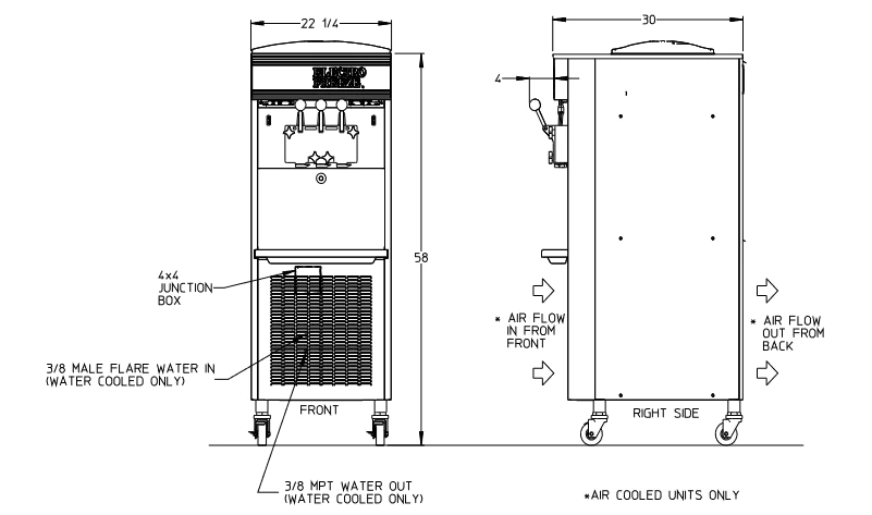
| Location | Dimension | Description |
|---|---|---|
| Front (Width) | 22 1/4" | Width of the machine at the front |
| Right Side (Depth) | 30" | Depth of the machine from the right side |
| Junction Box | 4x4 | Size of the junction box |
| Water In | 3/8" Male Flare | Size of water inlet (for water-cooled units only) |
| Water Out | 3/8" MPT | Size of water outlet (for water-cooled units only) |
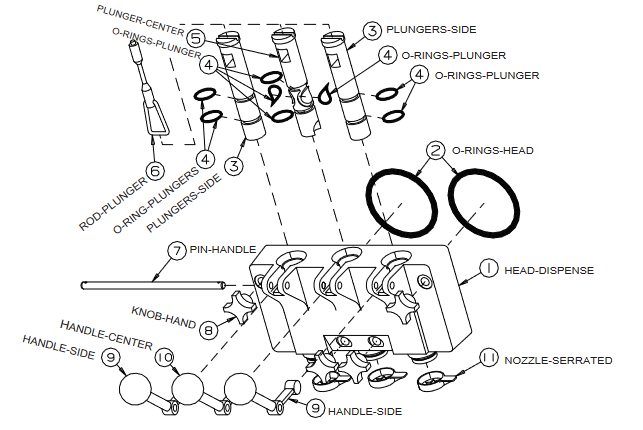
SL500 Faceplate Assembly
| Number | Part Name | Description |
|---|---|---|
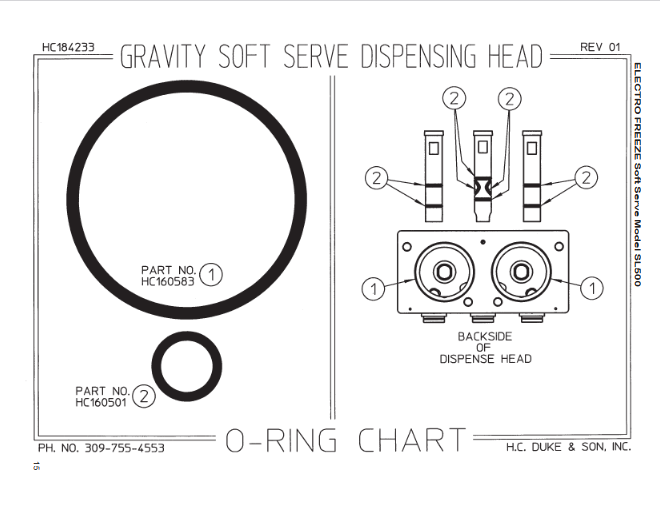
| 1 | HEAD - DISPENSE | Encloses the freezing cylinder and provides an opening for product to be dispensed. |
| 2 | O-RINGS - HEAD | Seals the head to the freezing cylinder. Must be lubricated. |
| 3 | PLUNGERS - DISPENSE - SIDE | Seals the product opening in the head when closed. Allows product to flow when open. |
| 4 | O-RINGS - PLUNGER | Seals the plunger in the head. Must be lubricated to seal and slide freely. |
| 5 | PLUNGER - DISPENSE - CENTER | Seals the product opening in the head when closed. Combines ice cream from both cylinders to form swirl cones. |
| 6 | ROD - PLUNGER | Starts the freezer when dispensing. Must be in place for proper operation. |
| 7 | PIN - HANDLE | Secures handle to the head. |
| 8 | KNOB - HAND | Secures the head to the freezing cylinder. |
| 9 | HANDLE - DISPENSE - SIDE | Opens and closes the plunger to start and stop the flow of product from the freezer. |
| 10 | HANDLE - DISPENSING - CENTER | Opens and closes the plunger to start and stop the flow of swirl product from the freezer. |
| 11 | NOZZLE - SERRATED | Forms the frozen product as it is dispensed. |
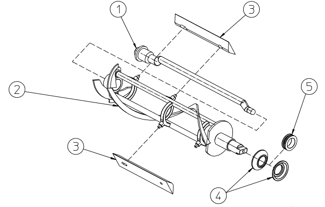
Beater Shaft Assembly
| Item | Part No. | Description |
|---|---|---|
| 1 | HC139913 | Bar-Breaker 16.02 in. |
| 2 | HC120866 | Shaft- Assy. Beater |
| 3 | HC141009 | Blade-Scraper |
| 4* | HC160557 | Seal-Beater Shaft |
| 5* | HC137593 | Washer-Double Shaft Seal |
| * Can be ordered together | ||
| HC115525 | Seal-Assy. Shaft Double | |
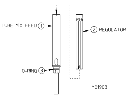
Mix Feed Tube Assembly
| Item | Part No. | Description |
|---|---|---|
| * | HC120676 | Tube- Assy Mix Feed Self Priming Complete |
| 1 | HC120672 | Tube-Assy. Mix Feed Self Priming |
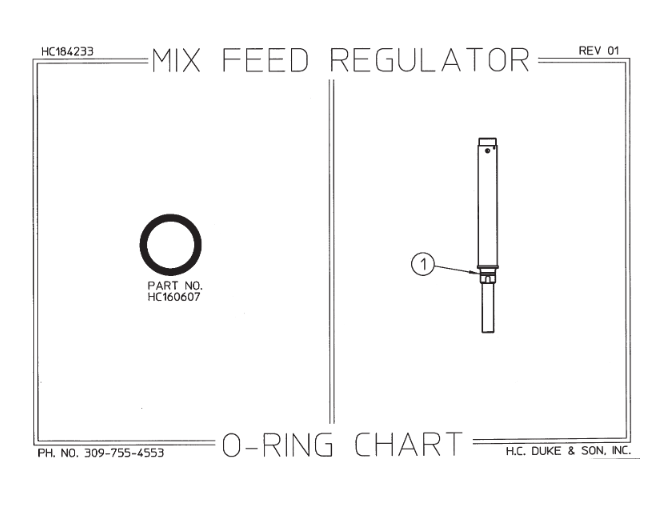
| 2 | HC137558 | Regulator-Mix Feed |
| 3 | HC160607 | O-ring (Mix Feed Tube) |
| * Includes all items above. | ||
O-Ring Charts for SL500 (Printable)
Other SL500 Accessories
| Part No. | Description |
|---|---|
| HC196103 | Bottle-Wash 500 ml |
| HC158009 | Brush-4 in. w/o handle (Handle p/n HC158012) |
| HC158003 | Brush-7/16 & 1-1/8 Double End |
| HC158077 | Brush-9/16 in w/36 in. handle |
| HC162105 | Caster-1-1/4 ST PT w/brake |
| HC162106 | Caster-1-1/4 ST PT w/o brake |
| HC184233 | Chart-O-ring EF Gravity SS (Laminated) |
| HC120858 | Cover-Assy. Control Switch 22 in. Open |
| HC196111 | Cover-Hopper |
| HC158012 | Handle-Brush Fiberglass (Brush p/n HC158009) |
| HC115536 | Kit-O-ring |
| HC158054A | Lubricant-Lubri-Film Plus 4 oz. tube |
| HC158000A | Lubricant-Petro-Gel 4 oz. tube |
| HC112978 | Leg-Assy. Six inch (Optional) |
| HC196185 | Nozzle-Serrated |
| HC150736 | Nut-Lock Conduit 1-1/4 (Casters) |
| HC158013 | Sanitizer-Stera Sheen (Sample) |
| HC158014 | Sanitizer-Stera Sheen (Per case/4 jars) |
| HC158014A | Sanitizer-Stera Sheen (Per 4 lb. jar) |
| HC158049 | Scale-Overrun |
| HC169374 | Tool-O-ring Removal |
| HC196270 | Tray-Drip 22 in. Black |
| HC184778-01 | DVD-Training |
Operator Controls and Indicators
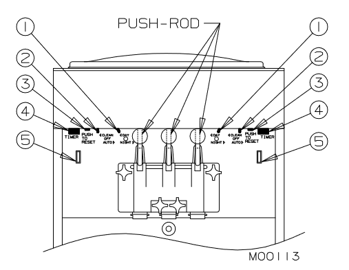
The following table describes the operator controls and indicators. Refer to the photo above for location of these controls and indicators on the freezer.
NOTE: The dispense head must be in place before the freezer will operate.
| Control | Description |
|---|---|
| Day-Night Switch (1) |
|
| Selector Switch(2) |
Do not use the “AUTO” position with water or sanitizer in the cylinder or hopper. The freezer will be damaged. |
| Reset — Overload (3) | If the overload trips frequently, your freezer should be checked for proper product temperature, overrun and voltage. Contact your Electro Freeze Distributor. This control protects the beater motor against failure from an overload condition by automatically shutting down the freezer. To restart the freezer properly, turn the SELECTOR switch to “OFF”, wait 2-3 minutes, then depress the red reset button and turn the SELECTOR switch back to the “AUTO” or “CLEAN” position. |
| Timer (4) | This control will bypass the thermostat, forcing the compressor and beater motor to run up to 3 minutes. Use the timer for quick start-ups or fast recovery when dispensing large portions. Excessive use of the timer causes freeze-up and damage to the freezer. |
| “ADD MIX” Indicator Light (5) | When blinking, this light indicates the mix in the hopper is at a low level and should be refilled as soon as possible. Always maintain at least 2 inches (5.1 cm) of mix in the hopper. For best operating results, keep hopper full. If proper mix level is not maintained, a freeze-up may occur and may damage the freezer. |
Mix Feed Tube & Regulator
This three-position regulating device meters the correct amount of mix and air into the freezing cylinder.
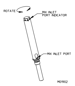
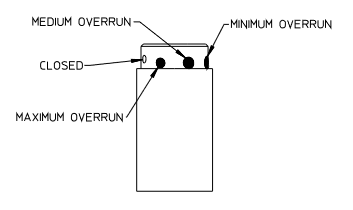
- Locate the round indent near the top of the mix tube cylinder. Align this indent to the center range of the three indent pattern on the mix feed regulator.
- The plastic mix feed regulator may be adjusted within the three indent range to obtain an optimum product overrun and dispense speed.
- The largest indent setting will allow the least overrun. The smallest indent setting will allow the most air in the cylinder and is used for a higher overrun. (see figure 5-4)
During periods of idle or night operation, place the mix inlet port to the closed position. At this setting, mix and air flow are shut off to the cylinder.
Important: If product is dispensed when the regulator is in the "CLOSED" position, a freeze-up will occur and may cause damage to the freezer.